Battery fires are once again in the news with a number of high-profile incidents in both stationary and motive applications. Here power management innovator Chris Hale looks at what thermal runaway is and what can be done to resolve the burning issue in lithium-ion batteries.
With the move to abolish the manufacture of internal combustion engine (ICE) vehicles by 2030, and the ever-increasing need for more energy storage sites to accommodate the move to greener energy production, thermal runaway mitigation is becoming ever more essential. Battery fires, aside from the health and safety aspects, have the potential to cause a huge amount of damage and cost exorbitant amounts to put right.
On 30 July, Neoen shut down its Victorian Big Battery energy storage system (ESS) in Australia, after a leak within the Tesla-supplied megapack cooling system caused a short circuit that led to a fire in an electronic component. The fire halted testing of the energy storage system for two months.
In August, vehicle maker General Motors (GM) began a $900 million recall after a torn anode tab and a folded separator on cells caused its Chevy Bolt electric vehicle (EV) battery packs to go into thermal runaway. Along with GM, there have been other high-profile recalls from automakers Hyundai Motors and Ford Motors within the last year; combined, there have been a reported 132,500 electric vehicles recalled at a cost of around $2.2 billion.
Early customers of Ford Motors’ Mustang Mach-E EV reported charging issues with the auxiliary 12V lead-acid battery. The problem, reported in April, was believed to have been a software issue preventing the auxiliary battery from charging if the drivetrain was plugged-in and charging the main lithium-ion traction battery. [This goes across the board, but the more sophisticated the battery packs need to be, the more likely software bugs will be seen to creep in. Preventing operation is one thing, managing safety is another].
Last year, Ford recalled around 20,500 Kuga plug-in hybrids in Europe, at a cost of around $400 million, to avoid risks of a vehicle fire when potential overheating concerns of the vehicle battery packs were identified. At the time Ford simply said: “We have identified that cell contamination in the drive battery system was the cause of the issue that a small number of Kuga PHEV vehicles experienced.”
At the beginning of the year, Hyundai Motors reported it would cost $900 million to recall its Kona EVs built between 2018 and 2020 following a reported 15 fires. In total, the OEM recalled 82,000 vehicles (including around 8,000 Ioniqs and electric buses, with Hyundai and its cell supplier LG Chem deciding to completely replace the batteries in the vehicles instead of trying to solve the issue through software updates).
Other significant recalls have included: Porsche, recalling its Taycan, their flagship EV, due to an issue with software in the battery management electronics causing the vehicle to completely lose power while driving (any number of false sensor readings may precipitate a safety shutdown within the battery). In fact, there have been a number of Auto manufacturers that have recalled EVs since their launch, due to battery-related issues and we can expect more to come.
Replacing combustion engines
At the end of the day, plans to adopt EVs as a primary replacement for ICE engines by 2030, and the increased use of energy storage systems (ESS), is going to add to the complication of cell supply and potential quality concerns beyond those of just software glitches. The “rare manufacturing defects” as declared by GM may not be as “rare” as we would like down the line.
To put this into context. In order to meet future cell demand, the Faraday Institute estimates the UK will need 140GWh of batteries per annum by 2040 for EVs alone, equivalent to the output of around seven UK gigafactories.
Then add on a requirement for global ESS projections of 1,300GWh by the same date— as forecast in the JRC science-policy report, Li-ion batteries for mobility and stationary storage applications— and the likelihood of a greater portion of “rare manufacturing defect” cells making their way on to the market becomes a little more worrying— and will undoubtedly result in a higher risk of battery-related fires— if more stringent mitigation strategies are not adopted.
It is worth pointing out that, generally speaking, lithium-ion technology is safe. However, with millions of consumers using batteries, failures are bound to happen. According to CASS industries in 2006, a one-in-200,000 breakdown using Sony cells, with a reported cause of microscopic metal particles, resulted in a recall of almost six million lithium-ion packs. The risk is that particles, on rare occasions, might breach the separators, leading to a short circuit within the cell.
If we consider cells with ultra-thin separators, which may be in the order of 24μm or less, and typical gigafactory dry rooms of ISO class 6 or 7 (Ref: cleanroom technology) allowing 293-2,930 particles >5μm per m3, it becomes a numbers game as to how often a cell may be compromised, especially as, with the advancement of higher energy density cells, separator layers get thinner.
Estimates are tricky on this as there are many unknowns but, according to 3M research, in 2016 the number of internal cell failures was estimated at 1:10,000,000 to 1:40,000,000 cells. Putting this into perspective, the lower order could equate to around 1 in 2,000 vehicles for an average 74kWh battery pack, or for 1MW energy storage container units using the same cells, equates to around 1 in 150 containers. The question is, what is this failure rate likely to be as we move forward with supply and demand, can we expect it to go up or down?
If a short circuit does happen, or the battery is abused, what are the mechanisms and what can be understood to minimise or mitigate the impact of a potential failure? To do this we must understand the sequence of events and stages of prevention, detection and containment.
Road to thermal runaway
The Runaway cycle: inevitably, as stated earlier, there will be cells that fail; whether through manufacturing defects, abuse or normal use. The questions of whether a failure can be detected in advance and what can be done to mitigate, or reduce, the severity will largely be down to cell-pack design and the sophistication of the battery management system (BMS) employed to monitor and protect the battery packs. Generally speaking, there is a pattern that can be demonstrated with the onset and cycle of thermal runaway. In essence, this amounts to two phases: prevention and containment.
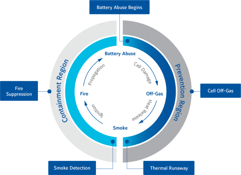
Prevention Region: As the name suggests, this is the period where detection and prevention are still possible. Any activity that can remove or reduce heat at this stage will slow or prevent progression and may yet halt thermal runaway.
Stage 1: Battery abuse/failure; the point at which cell damage begins to generate additional heat. Mechanical, electrical, chemical or thermal abuse, either internally-generated or from an external source, can cause temperature and internal pressure to rise. The cell will likely have a number of internal protection devices, a positive temperature coefficient (PTC) separator to protect against short circuits, and a current interrupt device (CID) to protect from overcharge, which may prevent further damage.
Stage 2: Off-Gassing. If the temperature and internal pressure continue to rise, the cell will begin to vent gas; an internal scored burst disk designed to release pressure will blow, permanently damaging the cell. At this point, external gas sensors can be employed to detect the critical failure but this is the critical point before thermal runaway and fire.
Stage 3: Thermal runaway. It is at this point where the internal cell temperature will rapidly rise and self-perpetuate until ignition temperatures are reached. As the cell internally reaches hundreds of degrees, smoke will be emitted and a catastrophic failure is now imminent.
Containment Region: With one or more cells reaching temperatures resulting in the exothermic breakdown of the electrolyte and melting of the separator, the internal pressure will increase, venting smoke, gas and flames.
Stage 4: Fire and propagation. When the internal temperature reaches the point of ignition threshold, the cell will burn rapidly spreading to adjacent cells and cascading through the pack. It is the pack and enclosure designs at this point that are now critical to minimise the destructive impact. Ensure that flame and ejecta aren’t restricted by pack construction and cell interconnections, to minimise the spread to adjacent cells. In order to direct, control or contain the escape of smoke and fire, pressure release valves, flame arrestors and the integrity of the battery enclosure should all be carefully considered.
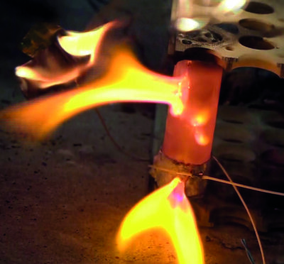
Containment deep dive: According to the report ‘Assessment of ISS/EVA Lithium-ion Battery TR Severity Reduction Measures’ published by NASA NESC in May 2017, there are five key Battery Design Guidelines for reducing the hazard severity from a single cell thermal runaway event. These are:
- Reduce the risk of cell-can sidewall breaches: As shown in Fig 2, if the can wall breaches, flames will be directed to the next adjacent cell. Most lithium-ion cylindrical cells these days have pressure relief vents at the top that will direct flames away from adjacent cells, provided battery pack construction isn’t restrictive and sends the heat back— i.e. using plates on top of the cell.
- Provide adequate cell spacing and heat rejection: direct contact between cells should be avoided, as it is a fairly sure way of transferring heat.
- Fusing of parallel cells: if a cell goes into thermal runaway it will short internally, presenting an external short condition for any other parallel-connected cells.
- Protect adjacent cells from ejecta: electrically conductive material (solids, liquids and gas) that can cause circulating currents affecting nearby cells.
- Prevent flames from exiting the battery enclosure: flame arresting screens and indirect paths to vent ports should be considered as well as ensuring any escaping flame is directed away from nearby critical systems.
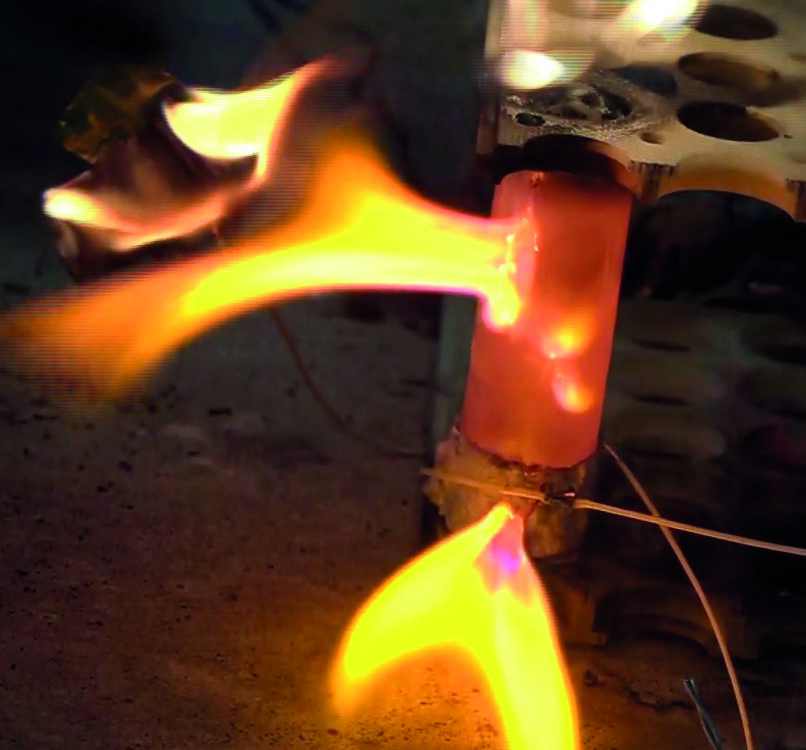
Fire protection— either prevention or containment— is critical, to ensure damage limitation and reduce the risks to health and safety. However, fire is not the only hazard that needs careful consideration. It should not be understated that toxic gas release can also present a very real hazard to health, and even if the cell doesn’t catch fire it may eject a huge volume of harmful smoke and fumes as shown in Fig 3.
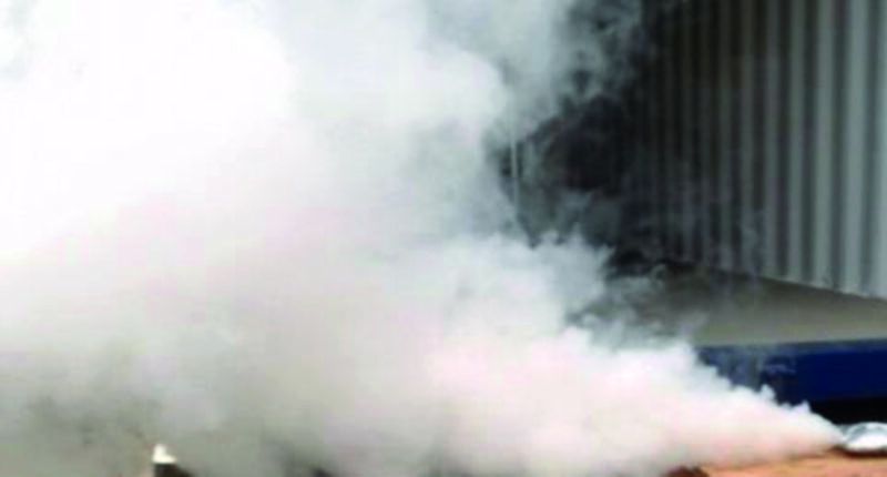
The bottom line is: there’s a huge number of complex gases that can be released, varying significantly from cell type to cell type; the most publicised of these is hydrogen fluoride (HF), produced from lithium salts, with almost three times the quantity released for a fully-charged cell as opposed to half-charged or empty. If hydrogen fluoride (HF) is dissolved in water it forms a very corrosive hydrofluoric acid.
To put things into perspective, according to the Research Institute of Sweden (RI.SE) report, Thermal propagation in lithium-ion batteries, the toxicity levels of hydrogen fluoride are 1.7 mg/m3— Allowed exposure level at work (Sweden); 25 mg/m3— Immediately Dangerous to Life or Health (IDLH) (30 minutes); 139 mg/m3— Lethal 10-minute value (AEGL-3).
As an example, if a 100kWh lithium-ion battery is consumed by fire it may emit 2-20kg HF, corresponding to a volume of 80,000-800,000m3, or in context to the immediate danger to life or health (IDLH) value, a volume of a large shopping centre.
So, a critical event can cause smoke and toxic gas, whether the cell does or doesn’t catch fire. However, it must also be taken into consideration that gas release (venting) can occur to a far lesser degree before, and without thermal runaway, and indeed at temperatures less than 100°C.
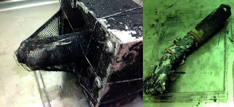
Venting, or even a gradual leakage of vapour, may occur, some of which may not be visible. Depending on the nature of vented gas, and if mixed with air in a confined space, there may be the added risk of gas explosion if ignited, i.e. from sparking, heated, or blown electronic/electrical components. This falls back again to pack design with provision to incorporate sufficient safeguards for material containment and pressure relief, including (as can be seen in Fig 4), provision for ejected material.
Reducing fire severity
Much of this article has focused on the impact of thermal runaway. However, if the cell temperature can be brought under control before ignition temperatures are reached, the severity can be reduced. At the end of the day, many battery packs, especially in the EV industry, will incorporate some form of thermal management, not only to maintain the operation of the battery at an optimum temperature level for performance and longevity but to assist in keeping a cell below ignition temperatures, should it start generating more heat than can be otherwise released.
This moves on to the choice of either active or passive thermal-management systems, which can be employed with varying degrees of effectiveness and risk mitigation; often dictated by mechanical complexity, cost and weight. Passive solutions will generally rely on convection/conduction plates and radiation, although the use of heat pipes or phase-changing materials (PCM) weaved in between cells can also be effective at absorbing heat quickly when their melting temperature (usually around 55°C) is reached.
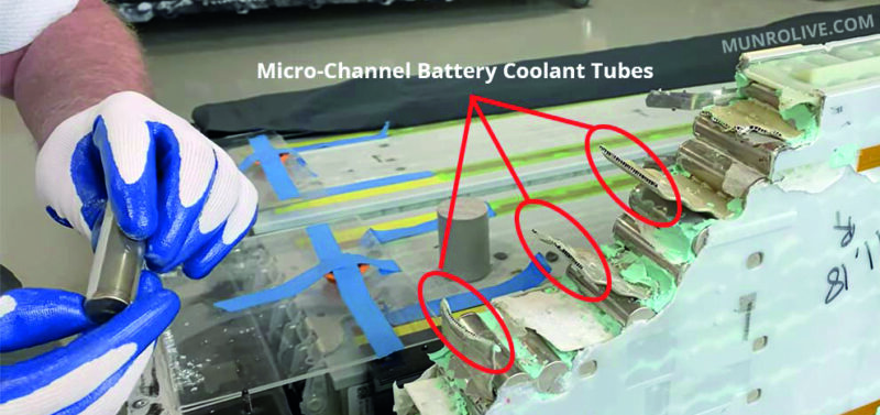
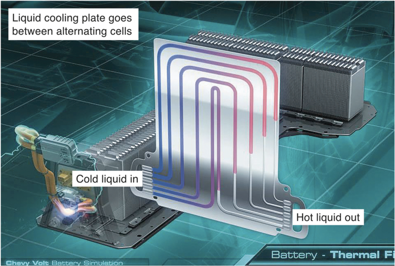
Active solutions on the other hand, such as those that use fans and pumps to force cooling, are generally more effective but ultimately mechanically more complex and expensive. Nonetheless, the solutions are used to effect in vehicles such as Tesla (fig 5) and Chevy Volt (fig 6).
Adding to cost
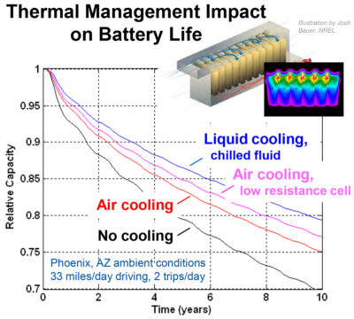
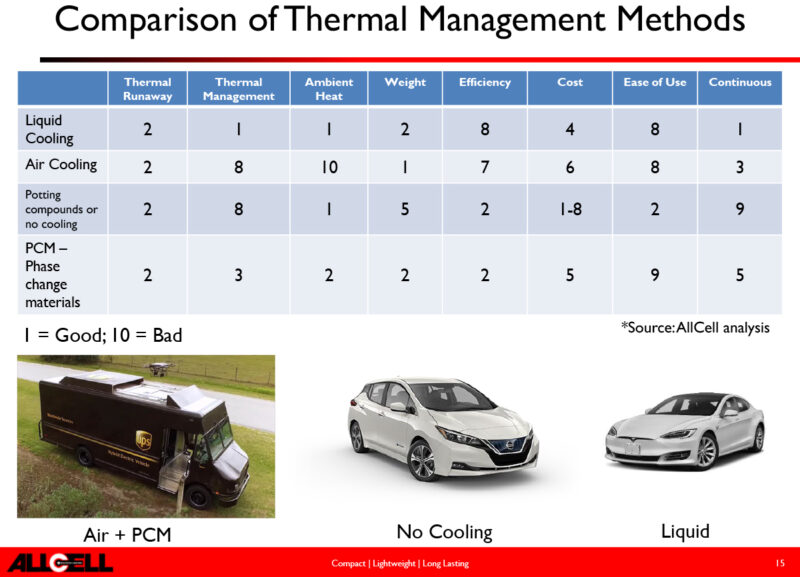
Thermal management does of course add to the cost, weight and size of a battery pack as a trade-off. However, apart from lowering the risk of thermal runaway, it does have the added fringe benefit of extending the useful life of the battery— so, in many applications, this alone provides good justification. From this aspect alone, the graph in fig 7, from eere.energy.gov, shows the impact on the longevity of various forms of thermal management approaches. In context, Table 1 provides an interesting comparison of three adopted vehicle solutions. Although you can make your own assessment of which is best, the point to note here is that they are all equally good in terms of thermal runaway.
