Isabella Mombrini, product specialist at Biologic, explains how lithium-ion batteries are not without their limitations and face various degradation mechanisms that can impact their performance and safety. As the demand for more reliable and efficient batteries grows, it becomes crucial to understand these degradation mechanisms and develop strategies for improving the design and operation of lithium-ion batteries.
The widespread adoption of commercial batteries has transformed modern living and working environments. Portable electronics are now integral to everyday life, with their usability and convenience largely dependent on the performance and reliability of their batteries. The success of electric vehicles is heavily reliant on the development of efficient and cost-effective batteries.
However, these batteries face limitations, like degradation mechanisms that affect their performance and safety. As the demand for more efficient and reliable batteries grows, it becomes essential to understand these degradation processes and develop solutions to enhance the design and operation of lithium-ion batteries.
Key innovation
Current research is focused on advancing battery technologies by improving energy density, accelerating charging speeds and ensuring better safety. Key areas of innovation include new materials, advanced electrode designs, and optimised electrolytes.
Operando studies, which entail real-time monitoring of a system’s behaviour under normal operating conditions, play a crucial role in battery research. By capturing electrochemical and mechanical changes as they occur during cycling, these studies provide essential insights into battery performance and degradation.
In particular, in situ operando studies focus on observing battery behaviour throughout the cycling process to investigate ageing and degradation mechanisms in battery materials and devices without altering the cell with any measuring device.
X-ray diffraction (XRD) is a powerful analytical technique used to investigate the crystallographic structure of materials. In battery research, XRD is utilised for in situ operando analysis by coupling the diffraction instrument with a potentiostat to monitor structural changes during charge and discharge cycles.
XRD works by analysing the interaction of X-rays with a material’s crystal lattice. When X-rays encounter a crystalline sample, they are diffracted at specific angles based on the atomic plane spacing within the lattice. By measuring these angles and the intensities of the diffracted X-rays, critical information about the material’s crystal structure, phase composition, and lattice parameters can be obtained. Through in operando XRD measurements, researchers can observe changes in the crystal structure of electrode materials as lithium ions intercalate and de-intercalate throughout the charge and discharge cycles.
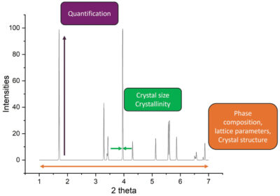
The peaks in a diffractogram reveal key details about the crystal structure, lattice parameters and symmetry of the materials (Fig 1). For example, shifts in the crystal structure, reflected in the diffractogram, can indicate stress, strain or phase transitions occurring during cycling.
XRD peak broadening is commonly used to estimate the particle size and distribution of active materials in batteries, while changes in peak shapes and positions can point to variations in particle morphology.
The intensity of XRD peaks reflects the degree of crystallinity in battery materials. Variations in intensity can signal changes in atomic ordering and packing within the crystal lattice.
Shifts in lattice parameters, peak positions, and intensities in XRD patterns provide valuable information on ion intercalation and deintercalation processes (e.g. lithium ions) in electrode materials during cycling.
In synchrotron facilities, multiple in situ operando X-ray diffraction experiments have been conducted on different commercial cells, with the goal to develop an analysis that can lead to non-destructive internal temperature measurements, and lithiation distribution across the volume, during cycling.
The goal is to provide an analysis that permits the study of different chemistries and cell size, with a high temporal resolution during operando cycling. This can provide tools to further fundamental understanding of cell operation and to improve existing cell and pack design, as well as developing new cell designs by providing new important data for simulations.
Advanced imaging
X-ray diffraction computer tomography (XRD-CT) is an advanced imaging technique that combines principles of X-ray diffraction (XRD) and computed tomography (CT) to provide detailed three-dimensional information about the internal structure and crystallographic properties of materials. It is particularly useful for studying polycrystalline materials, such as battery electrodes.
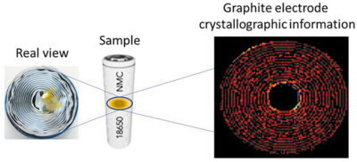
XRD-CT provides a 3D map containing diffraction information spatially distributed of the materials inside the sample. In other words, the final dataset is a 3D map where each pixel contains a distinct diffraction pattern. From diffraction patterns it is possible to obtain localised information regarding the crystallographic parameters and properties. This technique has been used for example to map a 18650 cell area during cycling (Fig 2).
This technique has been used, for example, to spatially resolve crystallographic phases and their evolution during cycling, in the negative electrode across 2D slices. By resolving lithium state transition inside the negative electrode, it is possible to identify the cause of capacity fade inside the device and damaged zone performance during cycling.
Two commercial LG INR18650 MJ1 cells, containing an LiNi0.8Co0.1Mn0.1O2 (NMC 811) positive electrode and a graphite/SiOx negative electrode were used in the experiment. One cell was measured in the pristine state at the beginning of life and was compared to an MJ1 cell cycled 1200 times to study the long-term cycling induced degradation. The changes occurring in the volume of an aged cell during cycling have been mapped by comparing the phase transitions and lithiation distribution of electrodes in an aged cell to those in a pristine cell.
Degradation and deformation
The aged cell showed a high degree of degradation and deformation after 1200 charge/discharge cycles, with a considerable capacity loss of 14.5%. The centre of the aged cell showed deactivation and loss of active material due to the physical deformation of the cell after long-term cycling. However, it was demonstrated that the damaged zone where the spirals collapsed were still partially active.
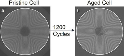
Another degraded zone inside the area of the aged cell was detected from the collapsed spirals going radially inside the area of the cell, enlightening that the loss of electrical contact showed by absorption CT was extended from the centre of the cell to the body (Fig 3).
By analysing an aged cell, it was found that the negative electrode did not reach fully delithiated stages in the entire volume at the end of the discharge, nor fully lithiated stages at the end of the charge. However, it was found that the collapsed region of the spiral in the centre (caused by mechanical deformation after 1200 cycles) was still partially active.
Uniform phase transition
The pristine cell showed a uniform phase transition across the volume, with a homogeneous lithiation distribution for both electrodes in charged and discharged stage; while the aged cell showed an inhomogeneous distribution of lithiation states at both charged and discharged stage in both the electrodes, highlighting the fact that after multiple cycles there is a decrease in the cell capacity and efficiency.
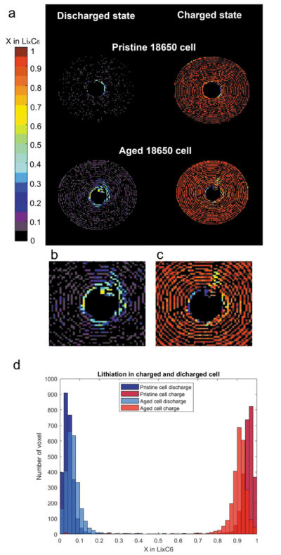
Fig 4b-c. Damaged zone extended into the volume from the centre, probably derived from spiral collapsing.
Fig 4d. Number of voxels vs x value in LixC6 at discharged and full charged state of aged cell.
Since each graphite phase is a distinct diffraction peak in the diffractogram, the lithiation in the negative electrode is expressed as the estimation of x in LixC6. This was determined by summing the lithium content from the measured stages of lithiation during the experiment. Therefore, the lithiation inside the two cells is expressed through the plot of x in in LixC6 across the battery volume as function of a coloured bar: the fully lithiated state in LiC6 is represented by dark red voxels. When the volume is black, the negative electrode is in the fully delithiated state, C6. The LiC12stage can be found at x=0.5 in light green coloured voxels.
Fig 4a shows the comparison between the pristine and aged cell at the end of a charge and at the end of a discharge. In the discharged state, the pristine cell showed a prevalence for voxels in a fully delithiated state and a few with x=0.05, showing almost full reversibility of the lithiation processes. On the other hand, the aged cell was not able to reach a fully discharged state and all the voxels show a distribution of x=0.05, 0.1, 0.15. Moreover, at the centre of the aged cell there is a mixture of x=0.5, 0.45, 0.4.
In the charged state, the pristine cell showed a homogenous fully charged state distribution, while the aged cell shows an inhomogeneous distribution of x=0.8, 0.85, 0.9. In this case, the centre of the aged cell shows a distribution of x between 0.2 and 0.6, indicating a multiplicity of lithiation states between
LiC30 and LiC12. The aged cell lithiation during charge demonstrated a general loss of activity in the cell’s centre.
The different lithiation distributions of the pristine and aged cells in the discharged and charged state is shown in Fig 4d, where the number of voxels containing a certain x in LixC6 are plotted as a bar chart for both cells. The aged cell showed a broader distribution of lithiation states, highlighting the fact that after multiple cycles there is a decrease in the cell capacity and efficiency across the negative electrode.
XRD-CT proved to be a useful technique to analyse material degradation into commercial cells. An important aspect is that with one test it is possible to acquire crystallographic information on all the cell component with a good spatial resolution (micrometers). Therefore, with one test it is possible to study the performance of electrodes, with the advantage of high spatial resolution across the cell volume over time and over different states of charge.


